|
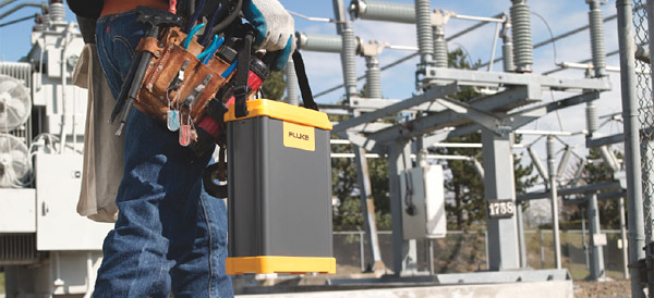
| Technical Specifications |
| 전력품질 측정기준 |
Conformance |
IEC 61999-1-4 Class 1, IEC 61000-4-30 Class A or B depending on measurement function, IEEE519, IEEE1159, IEEE1459 and EN50160 |
Clock/calendar |
Leap years, 2 4-hour clock |
실시간시계 정확도 |
Not more than ± 1 s/day |
내부메모리용량 |
At least 2 GB |
최대 레코딩 기간 |
At least 31 days |
측정시간 조정 |
Automatic |
최대 이벤트 수 |
Limited only by the size of the internal memory |
전원 |
100 to 2 40 V rms ± 10 %, 47-63 Hz, 40 W |
정전시 동작시간
(내부UPS동작) |
5 minutes per interruption, 60 minutes total operating time without recharging |
크기 |
215 mm x 310 mm x 35 mm (8.5 in x 12.2 in x 3.5 in) |
중량 (weight) |
6.3 kg (14 lb) |
|
| 입력 |
측정타입 |
One Phase Plus Neutral, One Phase IT No Neutral, One Phase Split Phase, Three Phase Wye, Three Phase Delta, Three Phase IT, Three Phase High Leg, Three Phase Open Leg, 2 Element Delta, 21/2 Element Wye |
입력채널 |
Voltage: 4 channels, ac/dc |
|
Current: 5 channels |
전압채널 |
Input resistance: 2 MΩ |
|
Input capacitance: < 2 0 pF |
전류입력특성 |
2 V rms = full scale, 1 MΩ Input Impedance for ferro CTs, low impedance for Flexi-CTs |
측정방식 |
Simultaneous digital sampling of voltage and current. Digital PLL synchronized sampling, internal frequency reference used during voltage drops. |
|
| 동기화, 샘플링 |
PLL-synchronization source |
The PLL synchronizes to the A-N voltage for wye power types, and to the A-B voltage for delta power types. All listed power types can be characterized as either wye or delta. |
PLL lock range |
42.5 to 69 Hz |
Sampling frequency |
Voltage and current: 2 56 samples/cycle Inter-harmonics per IEC 61000-4-7: 2 560 points/10 cycles (50 Hz), 3072 points/12 cycles (60 Hz) Transient Voltage: 5 MHz |
A/D resolution |
Voltage and current: 2 4 bits |
|
Transient voltage: 14 bits |
|
| 전압, 전류측정 |
전압측정범위 |
AC voltage: 1000 V rms ± 10 % over range |
|
DC voltage: ± 1000 V + 10 % over range |
전압 crest factor |
3 or less |
전류측정범위 |
Depends on current probe used |
전류 crest factor |
4 or less |
|
| RMS 전압 |
측정타입 |
True rms calculated continuously: every cycle, every 1/2 cycle, and every 10 or 12 cycles at 50 or 60 Hz respectively, as required by IEC 61000-4-30. |
측정불확도 |
AC: ± 0.2 % reading ± 0.1 % full scale, above 50 V rms |
|
DC: ± 0.5 % reading ± 0.2 % full scale, above 50 V dc |
|
| RMS 전류 |
| 측정타입 |
True rms calculated continuously: every cycle, every 1/2 cycle, and every 10 or 12 cycles at 50 or 60 Hz respectively, as required by standards |
|
| 과도전압 (impulse) |
측정타입 |
Waveshape sampling |
풀스케일 |
8000 V pk |
샘플분해능 |
200 nS |
측정불확도 |
± 5 % reading ± 2 0 V (test parameters: 1000 V dc, 1000 V rms, 100 kHz) |
|
| 전압 Swell(rms swell) |
측정타입 |
True rms (one cycle calculation by overlapping each half cycle - voltage between lines is measured for 3P3W lines and phase voltage is measured for 3P4W lines) |
표시데이터 |
Amplitude and duration of swell |
측정 |
Same as rms voltage |
|
| 전압 dip (rms sag) |
측정타입 |
True rms (one cycle calculation by overlapping each half cycle - voltage between lines is measured for 3P3W lines and phase voltage is measured for 3P4W lines) |
표시데이터 |
Amplitude and duration of dip or interruption |
측정 |
Same as rms voltage |
|
| Voltage dropout (interruption) |
|
| LAN interface |
연결 |
RJ-45 |
속도 및 타입 |
10/100 Base-T, auto MDIX |
통신프로토콜 |
TCP/IP over Ethernet |
|
| Wireless controller interface |
연결 |
wireless (2.4 GHz radio) |
속도 |
up to 700 kbit/second |
통신프로토콜 |
Bluetooth SPP |
|
| |
|
전력측정 |
| 전원, 배터리시간 |
|
True rms calculated continuously: every cycle, and every 10 or 12 cycles at 50 or 60 Hz respectively, as required by standards |
|
| 주파수 |
| 측정범위 |
42.5 to 69 Hz |
| 측정소스 |
Same as PLL synchronization source |
측정정확도 |
± 10 mHz (10 to 110 % of range, with sine wave) |
|
| Power Factor |
| 측정범위 |
0..000 to 1.000 |
| 측정정확도 |
± 1 digit from the calculation of each measured value (±3 digits for total) |
|
| Displacement power factor |
측정방법 |
Calculated from the phase difference between voltage fundamental and current fundamental |
측정범위 |
- 1.000 (leading) to + 1.000 (lagging) |
측정정확도 |
± 0.5 % reading ± 2 % full scale ± 1 digit |
|
| Voltage unbalance and phase sequence |
| 측정방법 |
Positive sequence voltage divided by negative sequence voltage, per IEC 61000-4-30 |
|
| Harmonic voltage and current |
분석창 |
rectangular |
분석순서 |
1st to 50th order |
측정정확도 |
Voltage / Current: 1st to 2 0th orders: ± 0.5 % reading ± 0.2 % full scale, 2 1st to 50th orders: ± 1 % reading ± 0.3 % full scale (current sensor accuracy must be included for current and power) |
측정방법 |
IEC 61000-4-7 |
|
| Inter-harmonic voltage and current (intermediate harmonics) |
| Analysis window |
rectangular |
Analysis orders |
1.5 to 49.5th order |
| 측정방법 |
IEC 61000-4-7 |
|
| 플리커 |
방법 |
IEC 61000-4-15 |
|
Plt for 2 hours and PSt for 10 minutes |
측정범위: |
0,1 to 5 (25) depending on voltage level, modulation and frequency |
|
|
|


))